Sensored Brushless Motor Controller (ESC)
Hall-sensored brushless DC motor controller designed for a 36 V bus. A three-phase MOSFET bridge, a dedicated half-bridge gate driver per phase and an STM32F401 controller on a single board.
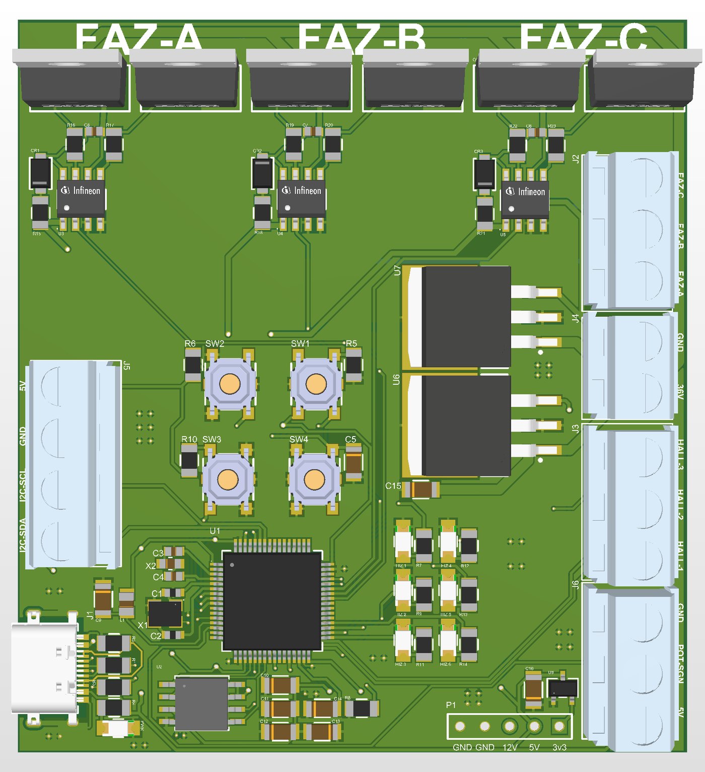
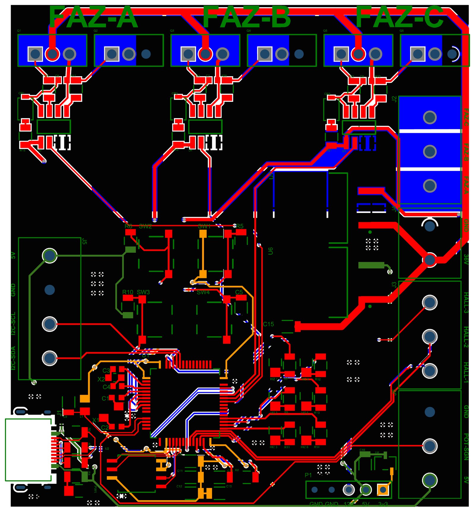
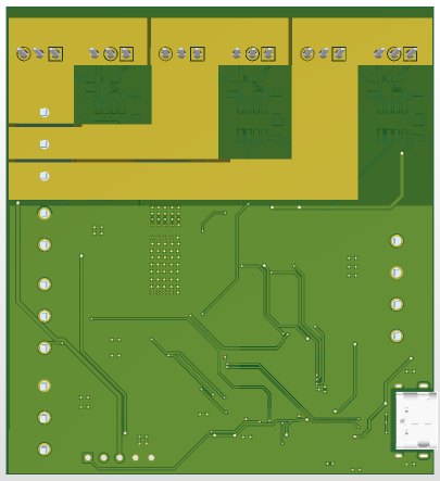
The board was designed to drive a brushless DC motor fed from a 36 V battery line, using Hall sensor feedback. The power stage, gate drivers, controller and user interface share one two-layer board. The high-current phase traces and MOSFETs sit along the top edge; the controller and logic circuitry are grouped in the lower section.
Architecture
- Power stage
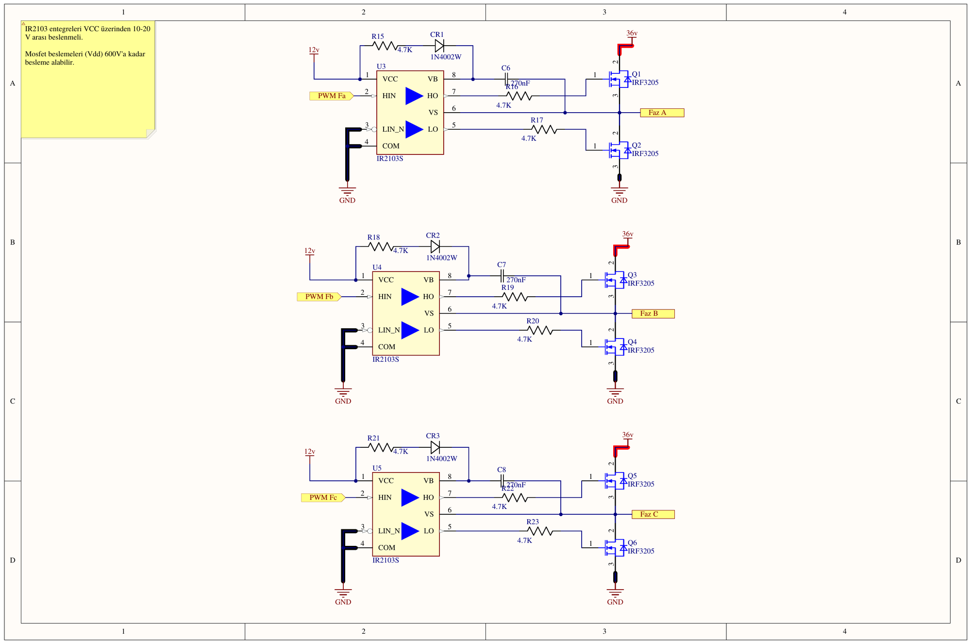
- A three-phase bridge built from three half-bridges, with two IRF3205 N-channel MOSFETs per phase.
- Gate drivers
- One IR2103S half-bridge driver per phase. The high-side MOSFETs are driven through a bootstrap circuit (diode and 220 nF capacitor); the drivers run from a 12 V rail.
- Controller
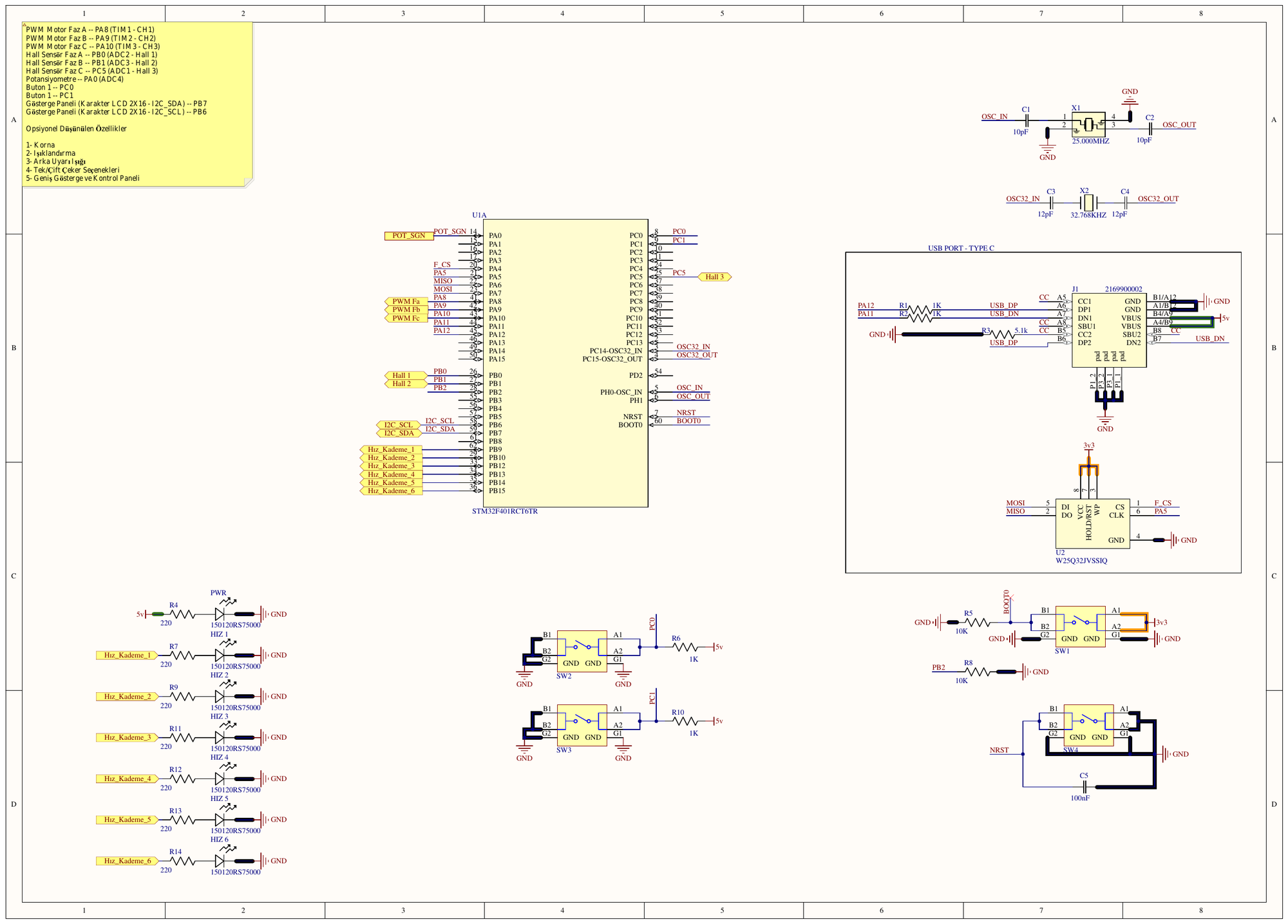
- STM32F401RCT6 (LQFP64) with a 25 MHz main crystal, a 32.768 kHz RTC crystal and 32 Mbit SPI flash (W25Q32).
- Feedback and input
- Three Hall sensor inputs, a potentiometer input for the throttle and four user buttons.
- Power distribution
- A 12 V rail for the gate drivers and 5 V and 3.3 V rails for the logic are derived from the 36 V bus.
- Interfaces
- USB-C connection and an I²C line for a 2×16 character LCD.
- Revision 2
- Current sensing and temperature protection are planned for the second revision.
Images
Click an image to open it in the viewer. Click it again to zoom in on the details.
Have a hardware idea?
Let's talk through the scope and technical constraints — I'll come back with a clear picture of the steps and the time it takes.